Appearance
Lab 1: Single Subnet Experiment
Learning Objectives
- Basic GNS3 Usage
- Understand L2 Forwarding (MAC address forwarding)
- Observe ARP operation process
- Learn IP address configuration
- Use Capture function to observe packets
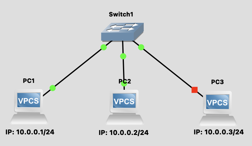
Topology Diagram
Background Knowledge
Network Protocol Layer Model
Network communication uses a layered model to organize protocols. Below is a comparison of the OSI model and TCP/IP model:
┌─────────────────────────────────────────────────────────────────────┐
│                    OSI 7-Layer Model vs TCP/IP Model                │
├───────────┬──────────────────────┬──────────────┬───────────────────┤
│ OSI Layer │   Layer Name         │  TCP/IP      │   Protocol/Tech   │
├───────────┼──────────────────────┼──────────────┼───────────────────┤
│    L7     │  Application Layer   │              │  HTTP, FTP, DNS   │
│    L6     │  Presentation Layer  │  Application │  SMTP, Telnet     │
│    L5     │  Session Layer       │    Layer     │  SSH, TLS/SSL     │
├───────────┼──────────────────────┼──────────────┼───────────────────┤
│    L4     │  Transport Layer     │  Transport   │  TCP, UDP         │
├───────────┼──────────────────────┼──────────────┼───────────────────┤
│    L3     │  Network Layer       │   Internet   │  IP, ICMP, IGMP   │
├───────────┼──────────────────────┼──────────────┼───────────────────┤
│    L2     │  Data Link Layer     │   Network    │  Ethernet, ARP    │
│    L1     │  Physical Layer      │   Access     │  Cable, Hub, NIC  │
└───────────┴──────────────────────┴──────────────┴───────────────────┘| Layer | Main Function | Covered in This Lab |
|---|---|---|
| L7-L5 (Application) | Provide network services for applications | ❌ |
| L4 (Transport) | End-to-end reliable transmission, flow control | ❌ |
| L3 (Network) | IP addressing, routing | ✅ (IP, ICMP) |
| L2 (Data Link) | MAC addressing, frame forwarding | ✅ (Switch, ARP) |
| L1 (Physical) | Bit stream transmission | ✅ (Cable) |
Ethernet frame
Ethernet frame is the Layer 2 packet format. Its structure is as follows:
┌──────────┬─────────┬─────────┬───────────┬─────────────┬─────┐
│ Preamble │ Dest MAC│ Src MAC │ EtherType │   Payload   │ FCS │
│  8 bytes │ 6 bytes │ 6 bytes │  2 bytes  │ 46-1500 B   │ 4 B │
└──────────┴─────────┴─────────┴───────────┴─────────────┴─────┘| Field | Description |
|---|---|
| Preamble | Used for synchronization (7 bytes) + SFD (1 byte) |
| Dest MAC | Destination MAC address |
| Src MAC | Source MAC address |
| EtherType | Indicates upper layer protocol (e.g., 0x0800 = IPv4, 0x0806 = ARP) |
| Payload | Actual data content |
| FCS | Frame Check Sequence, used for error detection (CRC-32) |
MAC Address Format
MAC address is a 48-bit hardware address, typically represented as 6 groups of hexadecimal digits: AA:BB:CC:DD:EE:FF
L2 Forwarding (Layer 2 Forwarding)
How does a Switch forward packets?
- Learn: When receiving a packet, record the source MAC and incoming port
- Lookup: Check if destination MAC is in the MAC Table
- Forward:
- Known → Send out from corresponding port
- Unknown → Broadcast to all ports (Flooding)
ARP (Address Resolution Protocol)
When PC1 wants to communicate with PC2, it needs to know PC2's MAC address:
PC1: "Who has 10.0.0.2? Tell 10.0.0.1"  (ARP Request - Broadcast)
PC2: "I am 10.0.0.2, my MAC is XX:XX:XX"  (ARP Reply - Unicast)
Steps
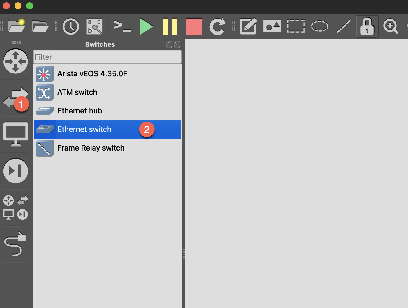
Step 1: Build Topology
- Open GNS3
- Drag in 1 Ethernet switch
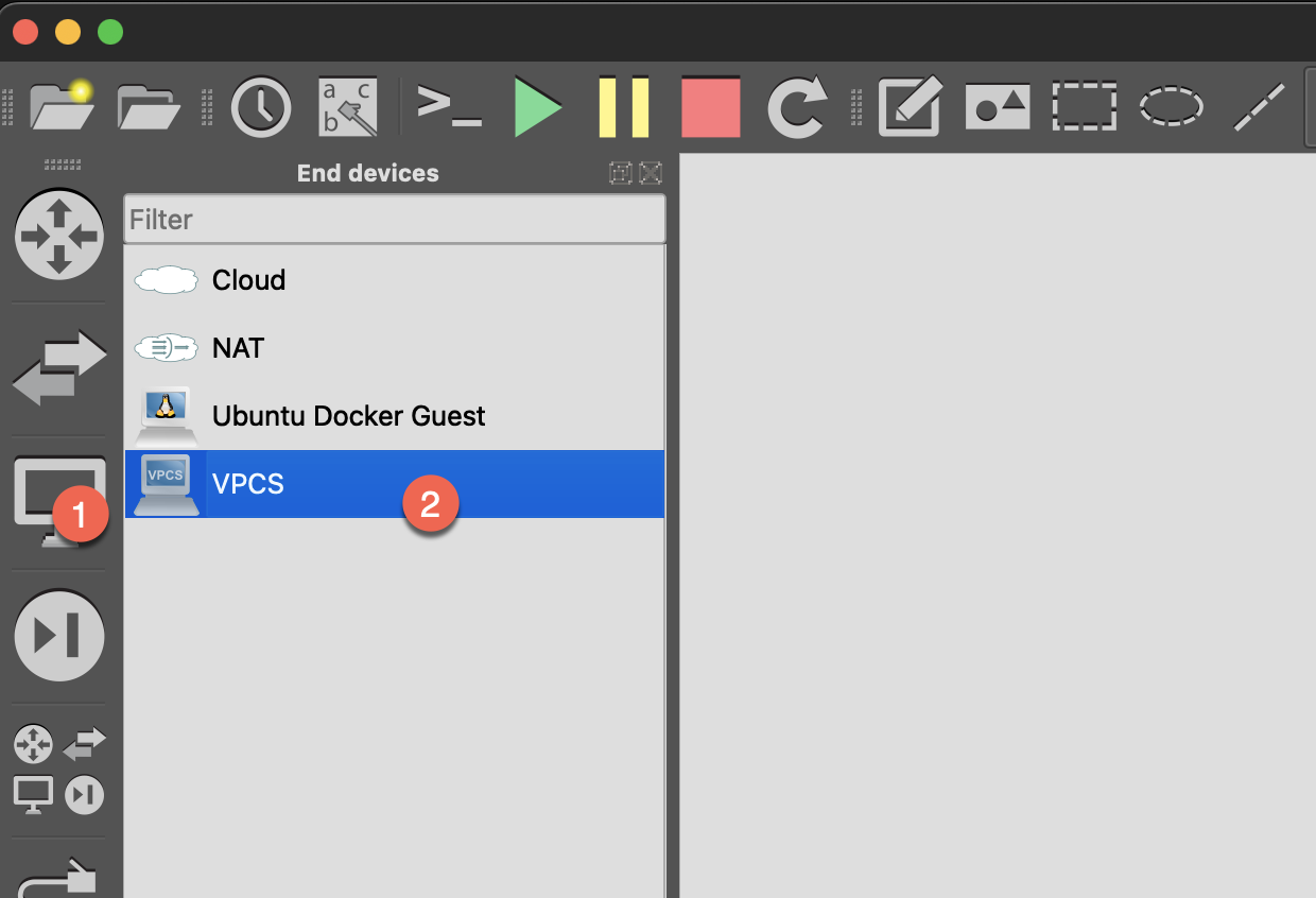
- Drag in 3 VPCS (as end hosts)
- Connect links:
- PC1 ↔ Switch (eth0)
- PC2 ↔ Switch (eth1)
- PC3 ↔ Switch (eth2)
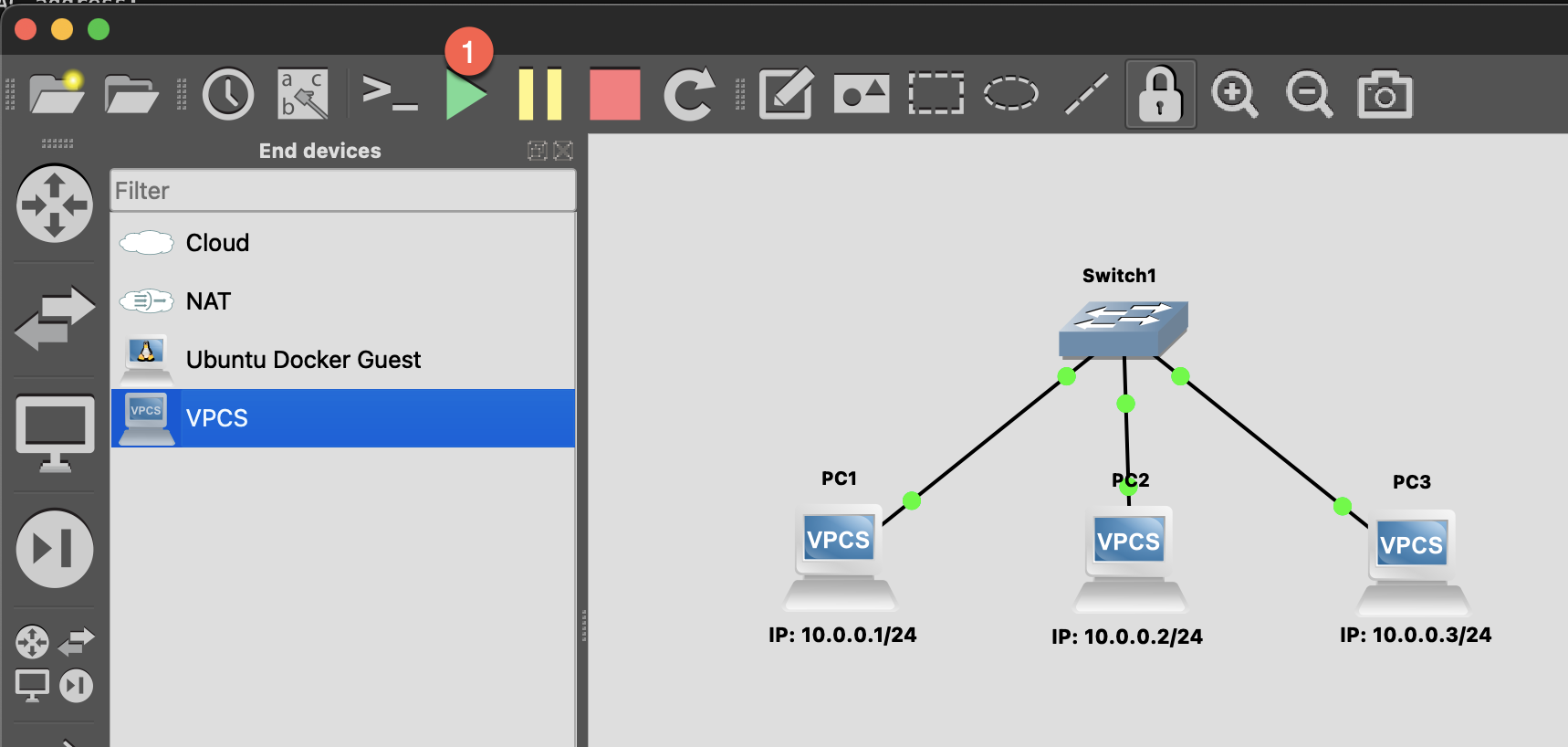
- Start all devices
Step 2: Configure VPCS
Set IP on each of the three VPCS:
PC1:
ip 10.0.0.1/24PC2:
ip 10.0.0.2/24PC3:
ip 10.0.0.3/24Step 3: Test Connectivity
Execute on PC1:
bash
# ping PC2
ping 10.0.0.2

# ping PC3
ping 10.0.0.3

# View ARP table
arp
Packet Capture Experiment
Observe ARP Process
- Right-click on the link between PC1 and Switch → Start capture
- Wireshark will open automatically
- Clear ARP cache on PC1:
clear arp - Execute
ping 10.0.0.2 - Observe packets in Wireshark:
Frame 1: ARP Request
  Who has 10.0.0.2? Tell 10.0.0.1

Frame 2: ARP Reply
  10.0.0.2 is at xx:xx:xx:xx:xx:xx

Frame 3: ICMP Echo Request
  10.0.0.1 → 10.0.0.2

Frame 4: ICMP Echo Reply
  10.0.0.2 → 10.0.0.1
Extend: Replace Switch with a Linux Docker Appliaces
Step 1: Replace Switch with a Linux Docker Appliaces
Step 2: Configure Linux Switch
Double-click the Linux node to open Console:
bash
# Create Bridge (software switch)
ip link add br0 type bridge
ip link set br0 up

# Add physical interfaces to Bridge
ip link set eth0 master br0
ip link set eth1 master br0
ip link set eth2 master br0

# Enable all interfaces
ip link set eth0 up
ip link set eth1 up
ip link set eth2 up

# Verify configuration
bridge link show
What is Bridge?
Linux Bridge is a kernel built-in software switch that can bridge multiple network interfaces together, just like a physical switch.
Observe MAC Table
On the Linux Switch:
bash
# View Bridge MAC learning table
bridge fdb show br br0
Discussion Questions
Q1: Why is the first ping slower?
Because the first time requires ARP resolution first, waiting for ARP Reply before ICMP can be sent.
Q2: What happens if PC2's network cable is disconnected?
- ping will fail (timeout)
- ARP Request will continue broadcasting but won't receive Reply
- After some time, ARP cache will expire
Q3: Does the Switch itself need an IP?
Not needed for pure L2 forwarding. Switch only looks at MAC addresses, not IP. However, if you want to remotely manage the Switch, you need to configure a management IP.
Next Step
After completion, proceed to Lab 2: VLAN Experiment