Appearance
Lab 2: VLAN Experiment
Learning Objectives
- Understand the purpose of VLAN (logical isolation)
- Configure Access Port
- Observe VLAN isolation effects
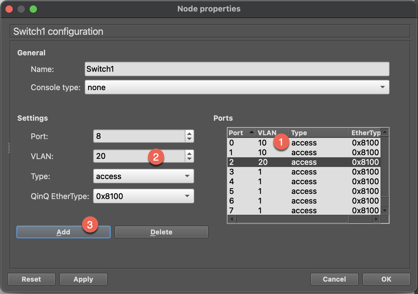
Topology Diagram
Background Knowledge
Why Do We Need VLAN?
| Problem | VLAN Solution |
|---|---|
| Broadcast Storm | Reduce broadcast domain |
| Security Isolation | Separate different departments/purposes |
| Flexible Management | No need to change physical wiring |
Port Types
| Type | Description | Use Case |
|---|---|---|
| Access | Belongs to only one VLAN, adds/removes Tag on entry/exit | Connecting end devices |
| Trunk | Can carry multiple VLANs, preserves 802.1Q Tag | Connecting switches |
802.1Q Tag
Inserts 4 bytes into the Ethernet Frame:
┌──────────┬──────────┬───────────┬─────────┬──────┐
│ Dest MAC │ Src MAC  │ 802.1Q Tag│  Type   │ Data │
│  6 bytes │ 6 bytes  │  4 bytes  │ 2 bytes │      │
└──────────┴──────────┴───────────┴─────────┴──────┘
                           │
                    ┌──────┴──────┐
                    │ VLAN ID: 10 │
                    └─────────────┘
Setup Topology and PCs
Step 1: Build Topology
- Drag in 1 Ethernet Switch
- Drag in 3 VPCS
- Connect:
- PC1 ↔ Switch (E0)
- PC2 ↔ Switch (E1)
- PC3 ↔ Switch (E2)
Step 2: Configure VPCS
PC1:
ip 10.0.10.1/24PC2:
ip 10.0.10.2/24PC3:
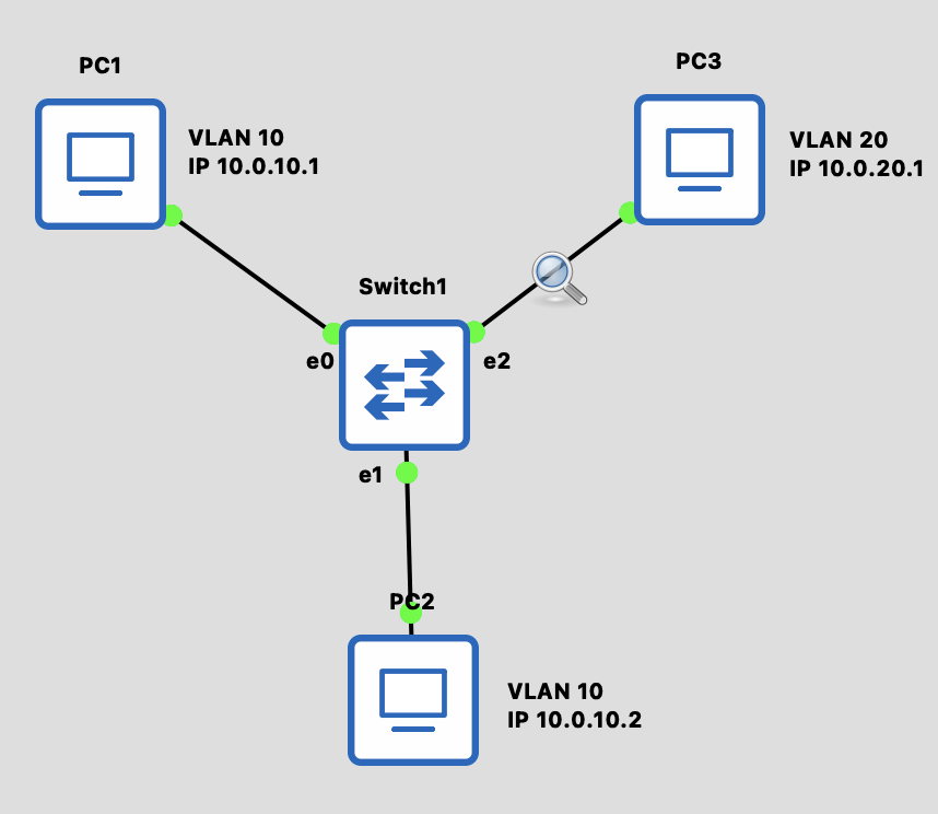
ip 10.0.20.1/24Before configuring VLAN, let's see what happens
- Start Capture between PC3 and Switch
- PC1 ping PC2
bash
# PC1 ping PC3 (both VLAN 10)
PC1> ping 10.0.10.2
# ✅ Should succeed!- Observe: PC3 can see the ARP packet
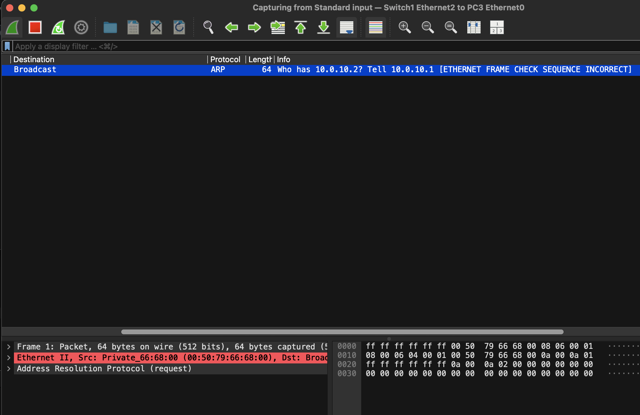
Configure VLAN on Switch
Right-click the switch and select Configure
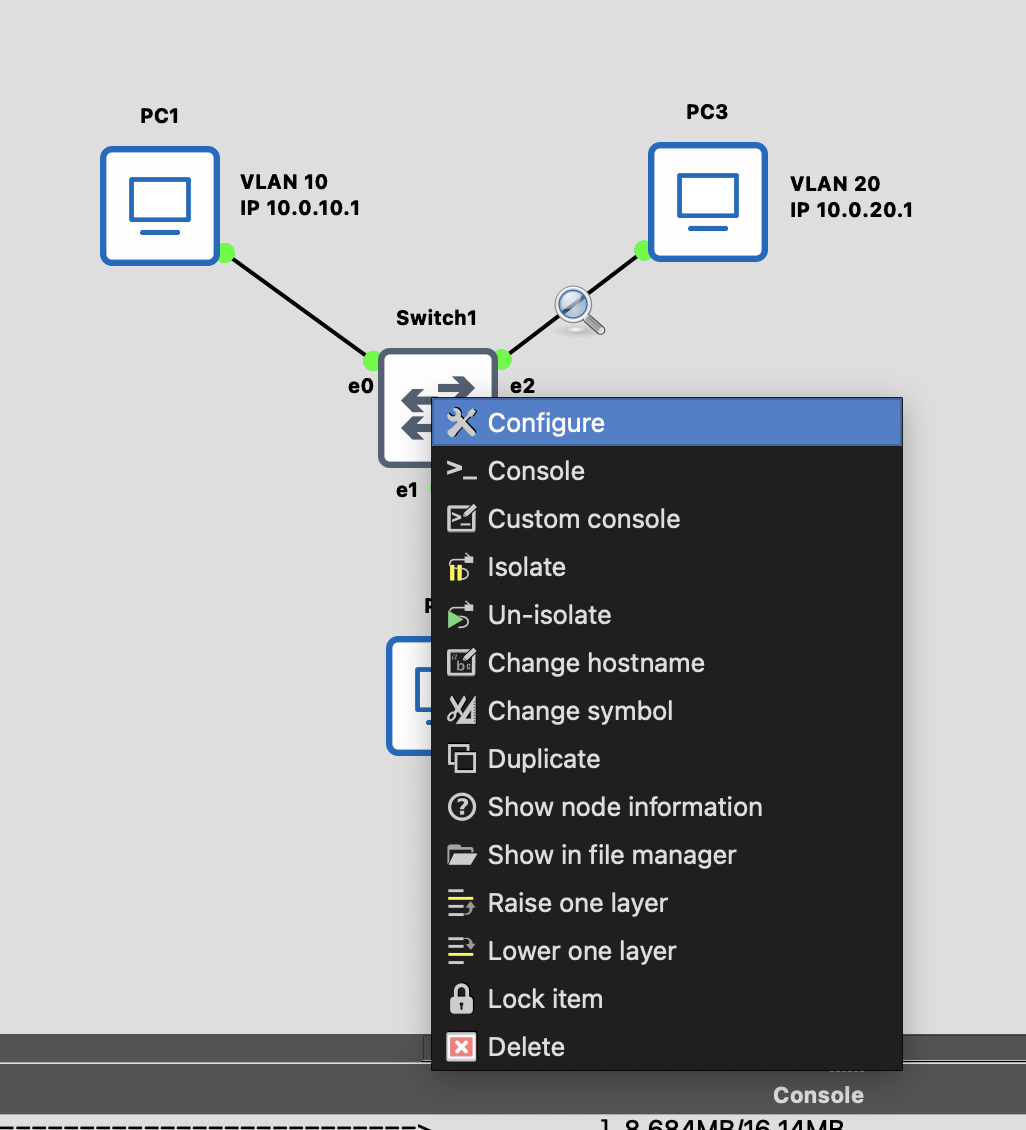
Double-click on the port, modify the VLAN then click Add
Confirm the following and click OK
- Port 0: VLAN 10
- Port 1: VLAN 10
- Port 2: VLAN 20
Verify VLAN Isolation
- Start Capture between PC3 and Switch
- Clear ARP on PC1
bash
PC1> clear arp- PC1 ping PC2
bash
# PC1 ping PC3 (both VLAN 10)
PC1> ping 10.0.10.2
# ✅ Should succeed!- PC3 will no longer receive the ARP from PC1
Extend: Replace Switch with a Linux Docker Appliaces
- Create bridge and add links into bridge
bash
# Create Bridge with VLAN filtering enabled
ip link add br0 type bridge vlan_filtering 1
ip link set br0 up

# Add interfaces to Bridge
ip link set eth0 master br0
ip link set eth1 master br0
ip link set eth2 master br0

# Enable interfaces
ip link set eth0 up
ip link set eth1 up
ip link set eth2 up- Configure Access Ports
bash
# eth0 → VLAN 10 (Access Port)
bridge vlan add vid 10 dev eth0 pvid untagged
bridge vlan del vid 1 dev eth0

# eth1 → VLAN 20 (Access Port)
bridge vlan add vid 10 dev eth1 pvid untagged
bridge vlan del vid 1 dev eth1

# eth2 → VLAN 10 (Access Port)
bridge vlan add vid 20 dev eth2 pvid untagged
bridge vlan del vid 1 dev eth2

# Bridge itself also needs configuration
bridge vlan add vid 10 dev br0 self
bridge vlan add vid 20 dev br0 self
Parameter Explanation
vid 10: VLAN ID is 10pvid: Port VLAN ID, untagged packets will be assigned to this VLANuntagged: Remove VLAN Tag when sending out
- Verify VLAN Configuration
View on Switch:
bash
bridge vlan showExpected output:
port    vlan ids
eth0    10 PVID Untagged
eth1    10 PVID Untagged
eth2    20 PVID Untagged
br0     10
        20
Discussion Questions
Q1: If PC1 and PC3 are configured with IPs in the same subnet, what happens?
Even if IPs are in the same subnet, they still cannot communicate because VLANs are different. VLAN isolation is done at L2 layer.
Q2: How can VLAN 10 and VLAN 20 communicate?
Requires a Router or L3 Switch. This is the content of the next Lab!
Q3: What's the difference between Access Port and Trunk Port packets?
- Access Port: Add Tag on entry, remove Tag on exit
- Trunk Port: Preserve Tag, can carry multiple VLANs
Challenge Exercises
Advanced Exercises
- Add VLAN 30 and configure a fourth PC
- Try setting up a Trunk Port to connect two Switches
Next Step
After completion, proceed to Lab 3: Router Connecting Multiple Subnets