Appearance
Lab 3: Router Connecting Multiple Subnets
Learning Objectives
- Understand L3 Forwarding (IP routing)
- Configure Linux Router
- Understand the role of Gateway
- Observe cross-subnet packet delivery
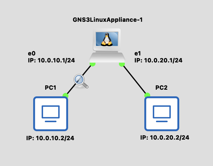
Topology Diagram
Background Knowledge
L2 vs L3 Forwarding
| Layer | Based On | Device | Scope |
|---|---|---|---|
| L2 | MAC Address | Switch | Same Subnet |
| L3 | IP Address | Router | Across Subnets |
IP Address
IPv4 Structure:
- 32-bit address divided into 4 octets (8 bits each)
- Written in dotted decimal notation:
A.B.C.D - Each octet ranges from 0 to 255
Example:
10.0.20.1  →  0x0A 00 14 01
   ↓  ↓  ↓  ↓
  10  0 20  1  (decimal)
Special Addresses:
- Network address: First IP in subnet (e.g.,
10.0.20.0/24) - Broadcast address: Last IP in subnet (e.g.,
10.0.20.255/24) - Loopback:
127.0.0.1(localhost)
Subnet mask -> CIDR (Classless Inter-Domain Routing)
CIDR Notation:
- Subnet mask
255.255.255.0→ CIDR:/24 /24means first 24 bits are network, last 8 bits are for hosts- Total addresses: 2^8 = 256 (254 usable hosts)
Common CIDR examples:
| CIDR | Host Addresses | Subnet Mask |
|---|---|---|
| /24 | 256 (254 usable) | 255.255.255.0 |
| /16 | 65,536 | 255.255.0.0 |
| /8 | 16,777,216 | 255.0.0.0 |
Why CIDR matters:
10.0.10.0/24and10.0.20.0/24are different subnets- Devices in different subnets need a router to communicate
What Does a Router Do?
- Receives a packet
- Checks the destination IP
- Looks up the routing table
- Decides which interface to send from
- Modifies the L2 header (changes to next hop's MAC)
- Decrements TTL by 1
Packet Transmission Process (Cross-Subnet)
When PC1 (10.0.10.2) sends packet to PC2 (10.0.20.2):
Check Destination Subnet
- PC1 applies the subnet mask to the destination IP
- Determines that 10.0.20.2 is NOT in the same subnet (10.0.10.0/24)
- Decision: Must send to the Gateway (10.0.10.1)
Resolve Gateway MAC Address
- Check the ARP cache for the Gateway's MAC address
- If not found, send an ARP Request: "Who has 10.0.10.1?"
- The router replies with its eth0 MAC address
Build and Send Packet (PC1 → Router)
- L3 (IP): Src=10.0.10.2, Dst=10.0.20.2 ← Final destination
- L2 (MAC): Src=PC1_MAC, Dst=Router_eth0_MAC ← Next hop
- Sends the packet to Switch1
Router Receives and Forwards
- Looks up the routing table: 10.0.20.0/24 → eth1
- Checks the ARP cache for PC2's MAC
- If needed, sends an ARP Request on the eth1 interface
- Rewrites the L2 header: Src=Router_eth1_MAC, Dst=PC2_MAC
- L3 remains unchanged: Src=10.0.10.2, Dst=10.0.20.2
- Decrements TTL by 1
- Sends the packet to Switch2
PC2 Receives Packet
- Switch2 forwards to PC2 based on the MAC address
- PC2 checks that the destination IP matches itself
- Accepts and processes the packet
💡 Key Point
The IP address stays the same throughout the journey, but the MAC address changes at each Layer 3 hop (router).
Steps
Step 1: Build Topology
Use Docker Appliances
You can use the Linux appliance created in the Create Docker Appliances guide as the Router.
- Add 1 Linux appliance (as Router)
- Add 2 VPCS devices
- Connect:
- PC1 ↔ Router (eth0)
- PC2 ↔ Router (eth1)
Step 2: Configure Router
bash
# Enable IP forwarding
echo 1 > /proc/sys/net/ipv4/ip_forward

# Configure interface IPs
ip addr add 10.0.10.1/24 dev eth0
ip addr add 10.0.20.1/24 dev eth1

# Enable interfaces
ip link set eth0 up
ip link set eth1 up

# View routing table
ip route show
⚠️ Important
ip_forward is disabled by default! Without enabling this option, Linux won't forward packets.
Step 3: Configure VPCS
PC1:
ip 10.0.10.2/24 10.0.10.1- IP: 10.0.10.2
- Gateway: 10.0.10.1 (Router's eth0)
PC2:
ip 10.0.20.2/24 10.0.20.1- IP: 10.0.20.2
- Gateway: 10.0.20.1 (Router's eth1)
Verification
Test Connectivity
bash
# PC1 ping Router eth0
PC1> ping 10.0.10.1
# ✅ Should succeed

# PC1 ping Router eth1
PC1> ping 10.0.20.1
# ✅ Should succeed (cross-subnet, through Router)

# PC1 ping PC2
PC1> ping 10.0.20.2
# ✅ Should succeed
View Router Routing Table
On the Router:
bash
ip route showExpected output:
10.0.10.0/24 dev eth0 proto kernel scope link src 10.0.10.1
10.0.20.0/24 dev eth1 proto kernel scope link src 10.0.20.1
Packet Capture Observation
Observe MAC Address Changes
- Start packet capture between PC1 and Switch1 (call it Capture A)
- Start packet capture between Router and Switch2 (call it Capture B)
- From PC1, run
ping 10.0.20.2
Capture A (PC1 side):
Src MAC: PC1's MAC
Dst MAC: Router eth0's MAC  ← Sent to Gateway
Src IP:  10.0.10.2
Dst IP:  10.0.20.2           ← Destination is PC2
Capture B (PC2 side):
Src MAC: Router eth1's MAC  ← Router changed it!
Dst MAC: PC2's MAC
Src IP:  10.0.10.2           ← IP unchanged
Dst IP:  10.0.20.2
💡 Key Observations
- IP addresses remain unchanged (unless NAT is performed)
- MAC addresses change at each router hop
- TTL decrements by 1 at each router hop
Discussion Questions
Q1: How does the Router know where to send packets?
Through the routing table. Each destination subnet maps to an egress interface or next hop.
Q2: With more subnets, do you need to manually configure routes?
You can use:
- Static routing: Manually configure routes using
ip route add - Dynamic routing: Use protocols like OSPF or BGP to automatically learn routes